-Originally published in the 2018 Facade Tectonics 2018 Annual Conference & World Congress Conference proceedings, Vol I.
INTRODUCTION
Green building design is continuously evolving to require a more holistic approach, especially with ever escalating concerns about climate change, rising CO2 levels, and progressive energy code cycles. California’s Title 24 Energy Code is moving towards net-zero energy for all new construction commercial buildings by 2030. This push in sustainability and efficiency makes it increasingly important for architects and engineers to collaborate early in design to ensure that the architectural intent of a building can be maintained while effectively meeting energy code with the project’s sustainability goals.
BACKGROUND
The Hollywood & Gower high-rise residential project is in the entitlement phase of its project life. HKS started the design process with conceptual ideas that maximized views and efficiency while minimizing costs. The team needed to understand how the various shading designs would reduce solar gains in the units, ensure a comfortable environment with a high window-to-wall ratio, and identify if the design would pass energy code. The intent of this analysis was to understand the quantitative benefit to designing external shading for a building. We attempted to understand first how design decisions impact sustainability and compliance on the project. Then, through the lens of the energy model, we wanted to help inform future design decisions for the project.
METHOD
Using Hollywood & Gower, a high-rise residential project, as an example, this paper discusses how architects and engineers should work together in the conceptual and entitlement phases to optimize a building’s design and ensure the design intent can meet energy code. In a more traditional approach to analyzing the energy in building, the architect brings on the energy analyst in the beginning of the schematic design phase, or once the project design requires compliance documentation for city approval. The former option carries less risk than the latter as there is still an opportunity to influence the design to increase efficiency earlier in the process. In the Hollywood & Gower scenario, the architect and energy modeler worked hand in hand to analyze different envelope options. The following stages detail the design processes and analysis phases from the initial ideas to preliminary compliance modeling results.
STAGE 1 – DESIGN IDEAS
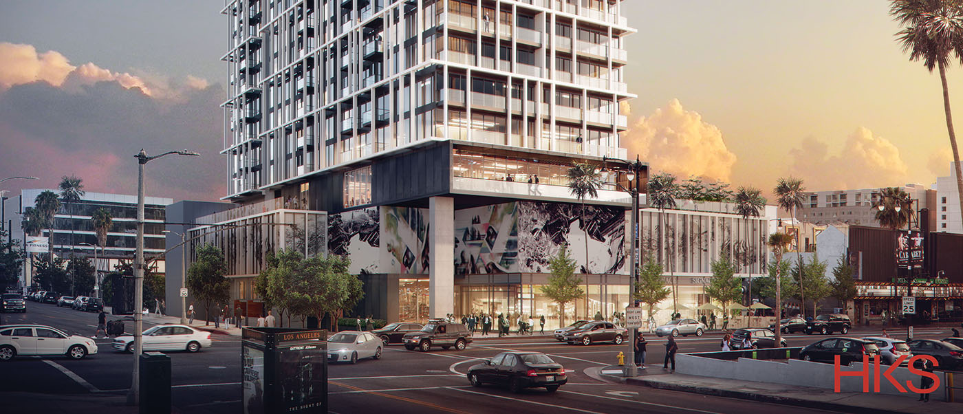
This proposed 22-story residential/mixed-use tower, located at the intersection of Hollywood and Gower, is generally regarded as being at the eastern gateway to the Hollywood Walk of Fame, where Lucille Ball’s star is at its front door. Its next-door neighbor, The Henry Fonda Theater, is a historically significant building and has hosted numerous high-profile live events. The tower, which contains 220 apartments, is designed for the young entrepreneur, or soon to be famous, stylish and hip-society type.
The tower is positioned on a north south axis to maximize views both to the north and the south for all units. To the north is a direct view to the Hollywood sign and to the south the Los Angeles city basin. On a clear day (yes we have them), the Pacific coastline and Catalina Island is visible. The orientation of the building also creates an opportunity for a sun-filled open space which acts as a “massing buffer” from the adjacent Fonda Theater and maximizes daylight entering the residents’ amenity space.
Several elevational/skin concepts were developed using Maya, a modeling, simulation and rendering software, for its ability to create rapid prototype concepts, each with an approach to creating a sustainable and performative skin that would preserve views and daylight but also protect against solar heat gain and glare.
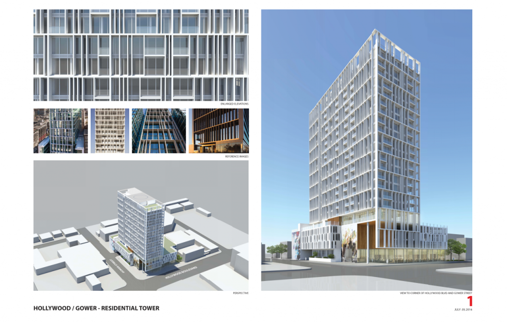
Scheme 1 was developed with the notion of connecting the building to the larger street-grid, scaffold supports and intense shading blurring the boundaries of the building edges. Rendering courtesy of HKS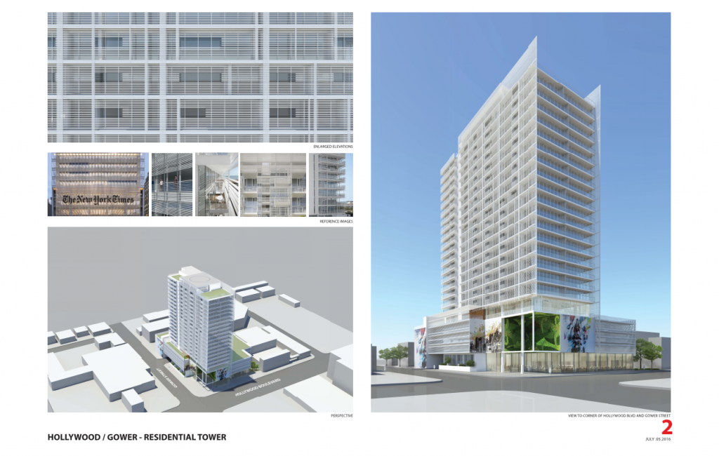 Scheme 2 took a far more measured approach and created a thin veil of metal tubes running horizontally, like venetian blinds only to be pierced by balcony openings. The second skin would extend beyond the footprint of the tower to emphasize the “superficial” nature and clearly identify the shading technique. In Scheme 1 and 2, the tower façade concept extended down to the podium levels tow rap and concealed parking and other uses.
 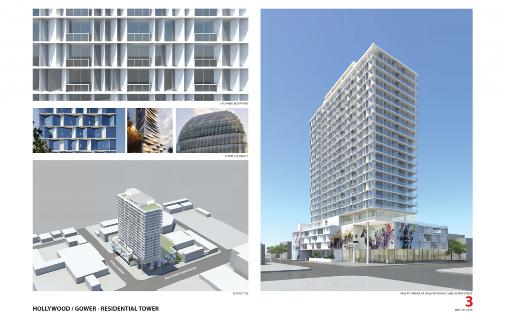 Scheme 3 utilized a series of horizontal “trays.” Between each floor tray is a fluctuating ribbon of vision glass, patterned glass and metal panel, creating a digitized pattern. Vision glass is located to maximize exposure into living spaces, while bedrooms were primarily glazed with patterned or screened glass.
 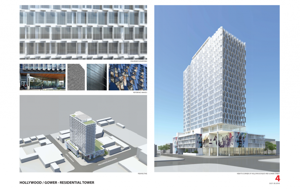 Scheme 4 established a series of shingled/angled glass panels in an attempt to create a skin resembling elements found in nature. Glass angles were set to maximize views and minimize solar heat gain. Panels on upper floors shaded the floor below and balconies could be added into each “cell” by removing glass selectively.
Probably the most striking feature of the tower will be its performative exo-skeletal bris-solei. Wrapped in a prefinished white aluminum panel, it was designed in hopes that it would:
- Maximize vision glazing around the building
- Create a foil which organizes the otherwise randomness of the “diving board” balconies. The skin is offset four feet, to create usable but structurally achievable platforms from the main structure in front of clear vision glass and dark metal mullions/panels. In a sense, the bris-solei becomes art and recalls the history of billboards, scaffolds and the structure of the iconic Hollywood Sign.
Full-length south-facing terrace balconies provide ample shading while not compromising views from the units. The rooftop features a full indoor prep kitchen, indoor activity room and landscaped terrace with outstanding views.
STAGE 2 – PRELIMINARY ENERGY MODELING – ARCHITECT
As described in the preceding section, the basic massing of the building and the options for shading structure – exo-skeletal bris-solei, were narrowed down based on various site parameters and restrictions, including view preservation strategies and aesthetics. Although it was obvious that any type of shading structure would have some positive impact on the energy consumption, it had not been quantified to help in the decision-making process. It was also important to determine how it would compare against a code-baseline building to make sure that it would meet code.
As a first step, the architects went through a rudimentary energy modeling exercise to quantify the comparative benefits of the selected shading strategies compared to a code-baseline building with no shading device. Additionally, this exercise informed the sensitivity of the window-to-wall ratio (WWR) to the performance of the building. The goal of the exercise was to identify a window to wall ratio for the design case combined with the shading structure that would meet the performance of a code-baseline building with no shading device and a 40% WWR.
The representative floor method was used to run energy simulations for the purpose of this exercise. A total of three floors were modeled. However only the results of the middle floor were used for calculations as the floors on the top and the bottom were only modeled to capture the boundary conditions, as would be the case in a typical floor in the residential tower. The model was created in Rhinoceros 3D and Honeybee for Grasshopper was used to run the energy simulations. Honeybee uses Energy Plus as its simulation engine. Although most of the geometry was created in Rhinoceros 3D, the windows were generated through Honeybee, which made it possible to control the WWR parametrically as a variable input.
The program of a mid-rise apartment was used to generate the default Honeybee model inputs for the simulations. The envelope parameters that were used are listed below:
- Roof insulation: R-27
- Wall insulation: R-8.7
- Window: U value 0.42; SHGC 0.28
Three sets of iterations were run, each with three variations. The first set was with no shading devices, with a window-to-wall ratio of 78%, 60%, and 40%. A 78% WWR was chosen as a maximum allowable. A 40% WWR is the ASHRAE 90.1 and Title-24 code baseline percentage that all energy models are compared against. The second set included horizontal shading devices with the same variations in WWR. The third set had the external frames as shading structure with the same variations in WWRs.
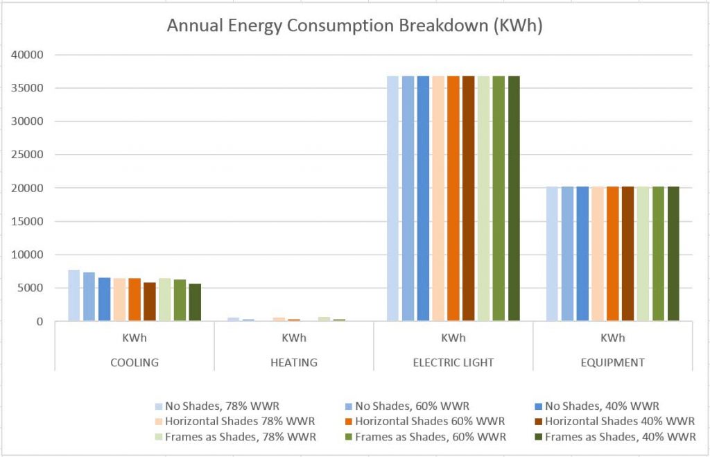
As the inputs for the electric light and equipment were kept constant, the results for those end uses show no change. The climate at the project site in Los Angeles (ASHRAE Climate Zone 3B, Title 24 Climate Zone 9) requires very little heating over the year, but has significant cooling needs. Thus, the load that the shading devices and the windows can impact the most is the cooling energy.
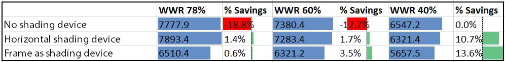
Isolating the cooling energy numbers, as shown in Figure 9, the option with shading devices at a WWR of 40% performs the best among the nine options, whereas the option with no shading at a WWR of 78% performs the worst.
The option with no shading device at a WWR of 40% was established as the baseline. With both horizontal shades and the frames as shading devices, the building could increase the WWR to about 60% and still perform better than the baseline (a percent savings of 1.7% and 3.5% in Table 1). However, the option of using frames as a shading device would perform better among the two. As the building has an elongated north-south orientation, and the east and west facades have maximum exposure, vertical shading elements of the frames at regular intervals proved beneficial to block solar radiation.
STAGE 3 – DETAILED ENERGY COMPLIANCE MODELING – ENGINEER
After the initial modeling effort, the team needed to see how the building was expected to comply with California Title-24 energy code. The team analyzed how the energy compliance margin was affected by different window to wall ratios and differing levels of exterior shading in the compliance model.
The project team modeled a three-floor representative section of the building. Using multipliers for a standard floor plate the energy performance of the entire residential portion of the building can be accurately extrapolated. The energy model was initially created in Revit to capture the full 3D geometry of the building. This was imported into CBECC-Com, the official state approved Title-24 compliance software. Based on previous experience with high-rise residential projects in Los Angeles, the team recommended that the representative residential portion of the building have a compliance margin of at least 3% better than code baseline.
The project team assessed the shading structure with various window-to-wall ratios in order to determine its effect on the energy code compliance. Three different window-to-wall ratios were analyzed, 40%, 60%, and 78% to match the preliminary energy modeling analysis. Each WWR was analyzed both with and without the shading structure for comparison and to see its effect on compliance. This assessment aims to determine how impactful the structure and WWR are on energy code compliance.
The following outlines all assumptions that were assumed as part of the basis of design for the Hollywood & Gower. These parameters were based on past project experience with high-rise residential towers in Los Angeles.
Envelope
- Exterior Walls U-factor of 0.122
- Roof insulation of R-30 insulation with cool roof finish (SRI 0.9)
- Window SHGC of 0.25 and U-factor of 0.42 (thermally broken frames)
HVAC
- HVAC was composed of central condenser water loop with water source heat pumps (WSHPs)
- Condensing boilers: 93% efficiency
- Closed loop fluid cooler with a 10F degree approach
- Dedicated outside air corridor ventilation unit (DOAS)
- Condensing DHW water heaters with 96% efficiency
- The residential unit WSHPs (17 EER, 5 COP) and ECM fan motors
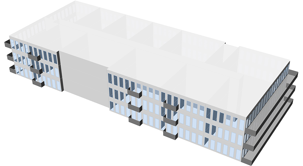
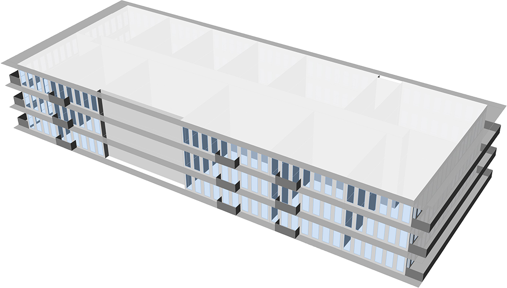
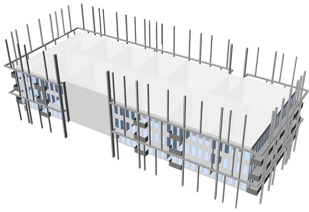
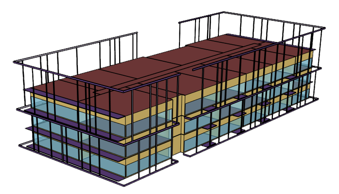
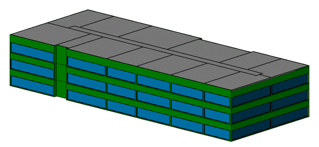
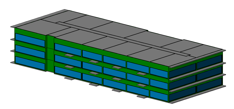
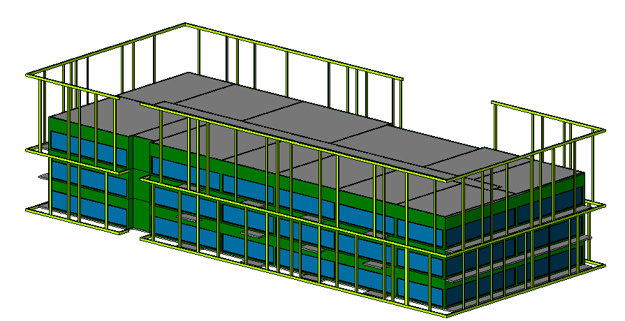
The building was also assessed for three shading options: no balconies or cage, balconies only, and with both the balconies and the cage. The Revit geometry models of each are shown in Figures 11-13, and the compliance results of these simulations are shown below in Table 2.
It was determined that that both the shading options and WWR had a significant effect on complying with Title-24. The 60% WWR with both balconies and the cage exceeded code by 1.2%, and would only require minor design changes to meet the recommended compliance margin.
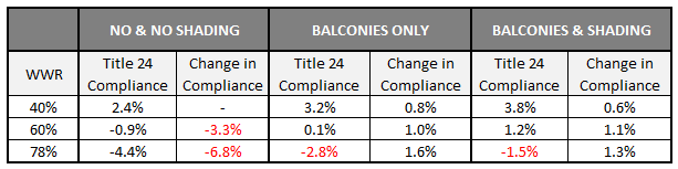
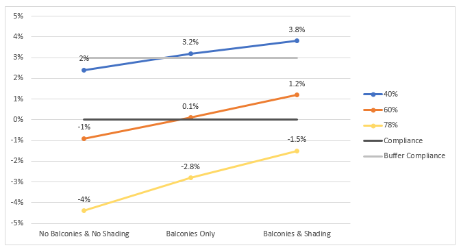
The 78% WWR design took a more significant compliance penalty of -6.8% relative to a baseline 40% WWR design. The balconies and cage shading structures were very helpful in reducing cooling-related loads and improved the compliance margin by 2.9%. This however did not make up for the overall penalty, and additional energy efficiency upgrades would be required to offset the increase in WWR, so additional energy efficiency measures are required in order to obtain the 3% target margin for a mixed use residential building. These energy efficiency measures could include high performance glazing, premium efficiency HVAC equipment, or a solar hot water system to offset the domestic hot water load.
EXPLANATION
The Honeybee and CBECC-Com models both show the same narrative, that an increase in window-to-wall ratio has a decrease in performance due to the increase in cooling loads. From this analysis, we can deduce that through the development of an energy model of the exterior shading of the building, the energy impact can be quantified and implications can be ascertained. By designing and modeling detailed exterior shading early in design, one is more flexible to create a more interesting building with a lower cooling load and larger windows. External shading design works best when it is validated both architecturally and by the design engineer in order to create an integrated design that adds to the building aesthetically as well as for energy performance. Without the integrated process, the systems will not be optimized for efficiency and could potentially add cost with minimal performance benefit. This type of early collaboration is critical to meeting sustainability goals such as Architecture 2030 or Title-24 Net Zero Energy.
CONCLUSION & FUTURE WORK
Because the architect worked hand-in-hand with both the initial energy modeler and the compliance energy modeler, every step of the external shading structure was analyzed. Performing these iterative energy analyses in the entitlement phase is critical. The entitlement phase sets a precedent for the project and creates some design constraints for the project moving forward. If the building design is floor-to-floor glazing in the entitlement phase, when the building goes through compliance the HVAC system will need to be able to mitigate the harsh solar loads and will end up increasing the cost of the building’s HVAC system.
The design of a 21st century building requires a holistic approach. Architectural and structural elements influence the mitigation loads required by HVAC (possibly saving on first cost) and can potentially lessen the energy requirements of the building. These up-front analyses help integrate different disciplines and assist in understanding the impact of design decisions early in the process. While this specific CBECC-Com analysis will resonate most specifically with people in California, the results and understanding span globally.
Moving forward, green building design will continuously evolve to include this holistic approach. With escalating concerns about climate change and CO2 levels in the environment, it is becoming evidently clear that even the highest standards of construction performance used today are not progressive enough. In order to hit Architecture 2030, it will not be enough to decrease the solar loads through the use of external shading. More passive strategies are needed, such as natural ventilation, night pre-cooling strategies, daylighting, solar tubes, designing with thermal mass, using perennial plants as shade walls, and optimizing solar penetration into the building for heating/cooling mitigation.

By optimizing the building for the climate in which it resides, the project can take advantage of “free” heating or cooling. These strategies can allow for reduced HVAC loads and can decrease first cost on HVAC systems and savings on utility costs throughout the project’s life. By tailoring the envelope and building design to incorporate natural lighting through daylighting or solar tubes, the project can decrease the amount of energy required to light the space while also providing a better environment for the tenant.
ACKNOWLEDGMENTS
Thank you to Brian Stern and Jacob Chan for their help with the analysis and report.
REFERENCES